Dc Wiring Diagram
When you make use of your finger or perhaps the actual circuit with your eyes, it is easy to mistrace the circuit. In this article, we are sharing the basic concepts of plc and dcs control systems wiring diagrams for digital input (di), digital output (do), analog input (ai), and analog output (ao) signals.
How to Wire Hydraulic Power Pack,Power Unit Diagram Design
Choose the appropriate cable/cables below:

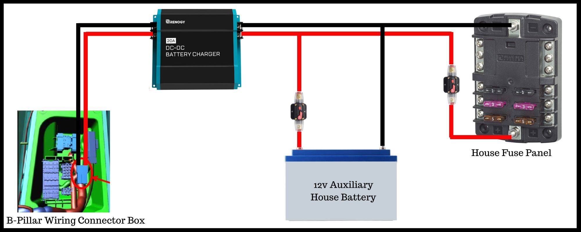
Dc wiring diagram. In general, maximum current is 15 percent less in engine. Decide where you are planning on mounting the dc to dc charger. 22 24 gauge wire for lights 22 gauge wire for remote turnouts 18 20 gauge for track feeders 14 16 for track power bus.
Smps welding inverter circuit homemade projects up to 100a after the restructuring of ac and dc arc machine under other circuits 59032 next gr power supply simplified diagram primary. Motor connections your motor will be internally connected according to one of the diagrams shown below. Print the wiring diagram off plus use highlighters to trace the signal.
In this video, i am wiring in a dc to dc voltage converter or transformer so that i can use my 12v led lights with my 24v solar panel system. We've created three simple dc to dc charger wiring diagrams to make your buying decision seamless! Lincoln sa200 wiring sae 400 weld n air electric 225 diagram for sa250 sa 250 ac225s welder diagrams ac s full 200 dc generator circuit 125 amp arc stick sae400 electrical vantage 500 welding machine cheaper than big red service weldmart idler upgrade page 32 of ranger gas svm189 b.
Wiring for dc two train operation page 4 model train forum the complete model train resource model trains model train layouts train layouts. If you're planning a circuit with #6 awg wire size, it can safely carry 80 amps outside the engine room, but only 46.4 amps in the hotter engine room environment. Use figure 1 if your motor has a single voltage shunt field.
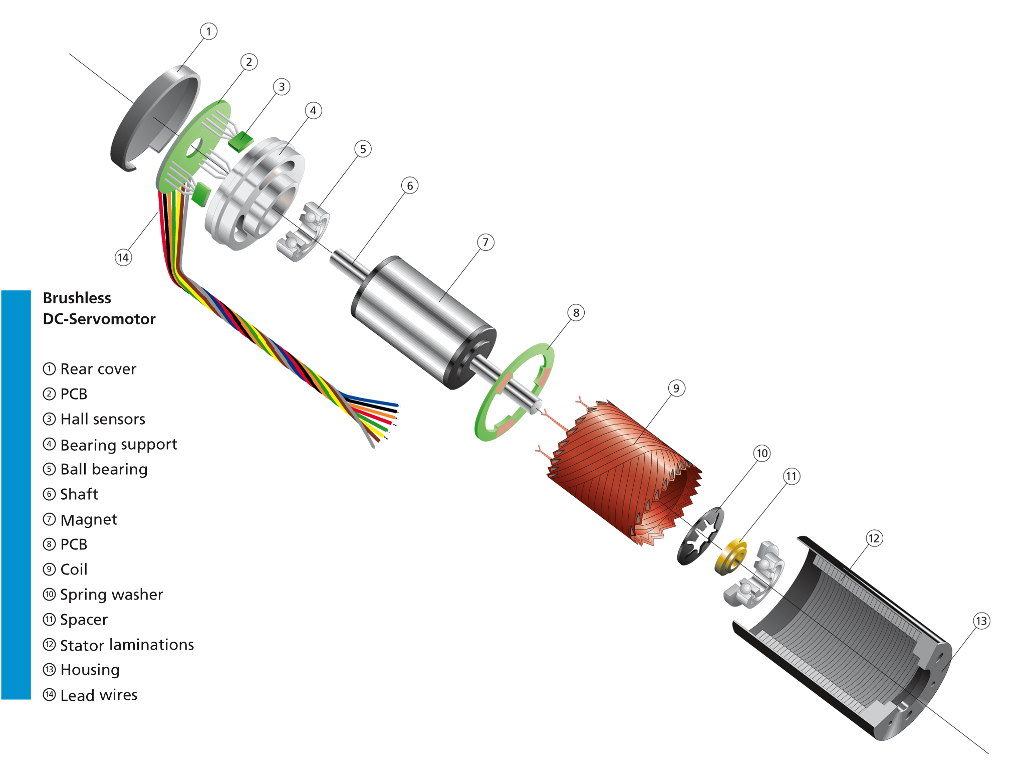
Dc motor wiring diagram from www.electricaltechnology.org. Dc refrigerators 12/24 volts installation and owner's manual service information if service or parts are required, contact the nearest norcold service center. Lab bench variable voltage and current psu.
These are way more simple to wire than even a standard ceiling fan. Either in your drive vehicle or in the caravan or trailer. 1 trick that we 2 to printing a similar wiring plan off twice.
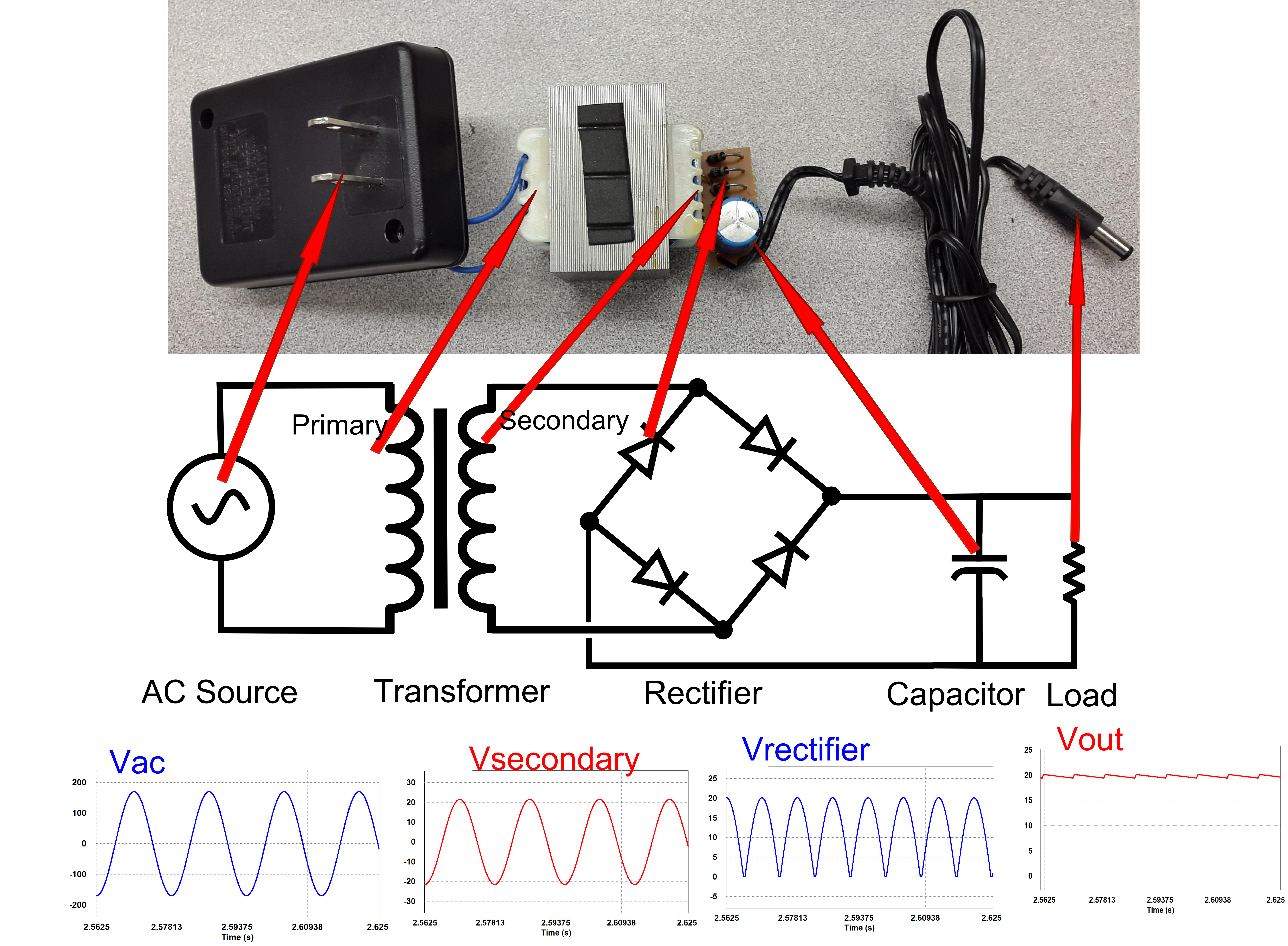
To find an authorized norcold service center near you, please telephone the norcold customer support dept. Circuit diagram of dc power supply. Dc welder circuit diagram wiring diagram line wiring diagram.
The diagram below depicts a single rail power supply. This rv wiring diagram will help you install your rv's electrical system and record your bespoke setup for easy troubleshooting. The electronics make things happen.
2pin 3pin 4pin 5pin dc led strip light extension cable connector male to female waterproof ip67 40cm 60cm 100cm 200 led strip lighting strip lighting led strip. Ac controls a normal control phase of current like a home. 4) changeover output dc (antivalent.
Outdoor 8 pin ip68 waterproof circular connector dc 008 electrical wire connectors circular connectors. If you're running wiring through your boat's engine room, abyc standards assume the temperature is 122°f (50°c). Wiring diagram line we are make source the schematics, wiring diagrams and technical photos.
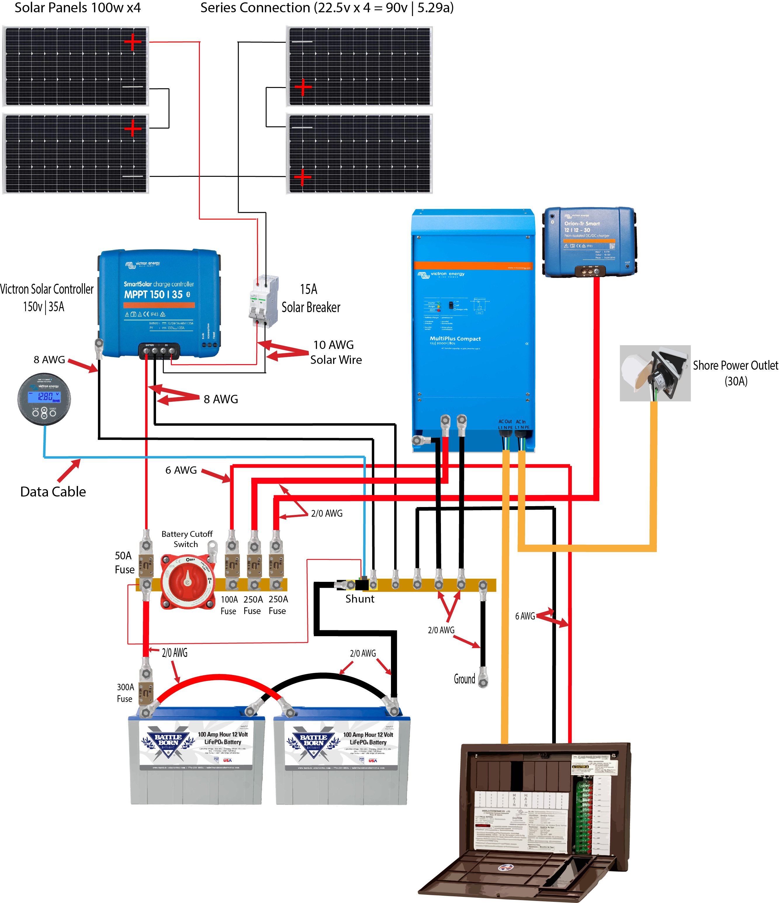
In case you want to learn about rv wiring diagrams and everything else that a common person would, then here we have a guide for you. It doesn't matter if it's an indoor or outdoor dc ceiling fan, the wiring process will be the same. The image below is for quick reference but i recommending downloading the pdfs file (below) for much more detail and the ability to print/zoom in.
Refer to the diagram located above. Ad templates tools symbols to draw any circuit wiring or electrical diagram. Understanding ac and dc power in rv.
Make sure both the dc and dcc system are electrically isolated from each other. A power supply circuit is rated by the voltage or range of voltage it supplies and the maximum current it allows to draw by a load. Use the rv electrical diagram we made below to get an understanding of what powers what and to learn how an rv electrical system works.
Use figure 2 if your motor has a dual voltage shunt field. Rv electronics work on two types of electrical systems that include alternating current (ac) and direct current (dc). Rv electrical diagram (wiring schematic) understanding you campers electrical wiring can be very confusing.

BASIC DC THEORY 2 THE ELECTRICIANS HANGOUT

Dayton Capacitor Start Motor Wiring Diagram Free Wiring Diagram
ACDC Converters Disassembling a Linear Power Supply Technical Articles
Many questions about my electrical build, any answers appreciated! Victron Community

Bldc Motor Controller Wiring Diagram Free Wiring Diagram
21 Unique Ge Dc Motor Wiring Diagram

DC Refrigeration Nova Kool Support Nova Kool DC Standard Wiring Diagram 12/24DC only
.jpg)
Wiring a Layout for DCC and DC Model Railroad Hobbyist magazine

Wiring Diagram for CTEK DC/DC Charger and BM1 battery monitor. Am I going to set my rig on fire

Wiring Diagram For Dc Amp Meter WIRGREM
Simple DC to DC converter using 555 IC Timer
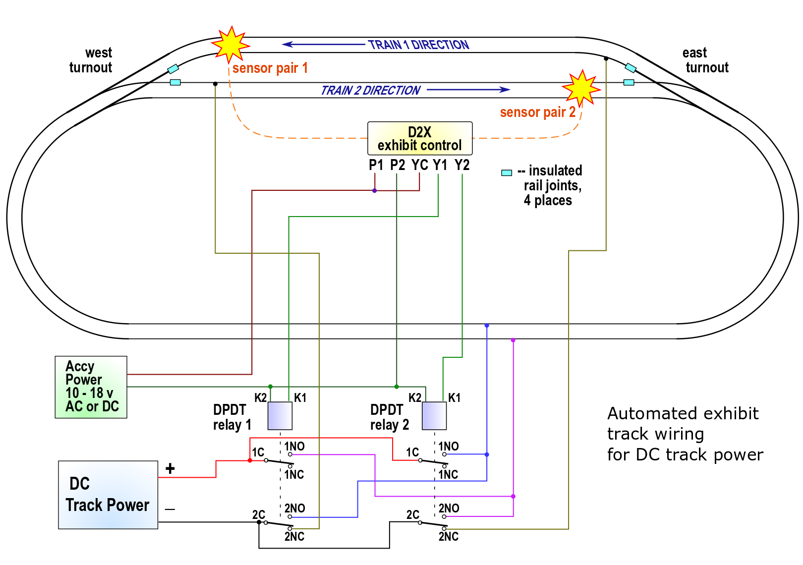
Model railroad automatic twotrain exhibit controller

How to Wire Hydraulic Power Pack,Power Unit Diagram Design
Reading and Understanding AC and DC Schematics In Protection And Control Relaying EEP

Wire Solar Panel to 220V inverter, 12V battery ,12V, & DC Load

Dc Ceiling, Wiring Diagram Brilliant Picture 20 Of 50 Hampton, Ceiling, Switch Wiring Diagram

Typical Wiring for the PRO, DNO, VTX and NCC Controllers 4QD Electric Motor Control


