Atv12h075m2 Wiring Diagram
Fr1˜= aiu1 [analog input virtual] (hz) To give you mechanical and electrical information related to the altivar320 drive, to show you how to install and wire this drive.
Installing Honeywell DT92E into Danfoss WB12 wiring box DIYnot Forums
Same day shipping most orders.
Atv12h075m2 wiring diagram. V connect the control part. Wiring a plug diagram wiring a 110v plug diagram wiring a 220v plug diagram wiring a dryer plug diagram every electric arrangement is made up of various diverse pieces. V connect the line supply, after making sure that the power is off.
Validity note original instructions and information given in this manual have been written in english (before optional This can be replaced by a 10 kω potentiometer (maximum). Shielded cable for connecting the control/signalling wiring.
Wire the drive (page 19) v connect the motor, ensuring that its connections correspond to the voltage. V set the motor parameters (in conf mode) only. Single phase power supply wiring diagram a1 drive km1 contactor only if a control circuit is needed p1 2 2 kω reference potentiometer.
8 bbv28590 06/2012 connection to rs485 bus connection to atv12 connection accessories should be ordered separately (please consult our catalogues). Sheet steel grounded casing not supplied with the drive, to be mounted as indicated on the diagram. Access to the line supply terminals to connect ring terminals.
Schneider electric atv12h075m2 vsd 1ph 0.75kw240v. Examples of critical control functions are emergency stop and overtravel stop. 4 way trailer connectors are.
Atv12h075m2 main range of product altivar 12. Torque in overspeed at constant power 2. Access to the terminals if you use stripped wire cables;
Log in to see recent orders. Pa and pc terminals, to the braking module dc bus. This can be replaced by a 10 kω.
V connect the control part. Schneider electric schneider electric atv12h075m2. V connect the line supply, after making sure that the power is off.
• the designer of any wiring diagram must take account of potential control channel failure modes and, for certain critical control functions, incorporate a way of achieving a safe state during and after a channel failure. This can be replaced by a 10 kω potentiometer (maximum). Gonzales a wiring representation is an easy visual representation of the physical links and also physical format of an electric system or circuit.
Blue electric brakes or hydraulic reverse disable see blue wire notes below in the trailer wiring diagram and connector application chart below use the first 5 pins and ignore the rest. The four wires control the turn signals brake lights and taillights or running lights. Seymour switches wiring diagram by using the download button or right select selected image then use save image menu.
V set the motor parameters (in conf mode) only. Connect the rj45 cable connector to the atv12 connector. For a single axle 14 gage is good but for tandem axles use 12 gage wire.
Heavy duty connector wiring diagram trailer wiring diagram trailer light wiring 5th wheel trailers. Connected as negative logic sink with external 24 vdc supply. This automobile is designed not only to travel one location to another but also to take heavy loads.
Inverter, atv12h075m2 1hp, 220v inverter, atv12h075f1 1hp, 110v 1 1 3u2 73050215 73050218 carriage inverter. V set the motor parameters in conf mode only. Plug 7 way trailer wiring diagram with brakes.
Ip20 without blanking plate on upper part. Fr1˜= ai1 tcc˜= 2c 9.2 10 loc 35.1 rdy 3s mode parameters factory settings: V connect the control part.
17 risk of drive destruction; 20 access to the power terminals. Nve41289 04/2016 9 about the book at a glance document scope the purpose of this document is:
It reveals the parts of the circuit as streamlined forms as well as the power and signal connections in between the gadgets. 4.2 electrical diagram sensor / limit switch location. Configure the drive page 31 v apply input power to.
Wire the drive (page 20) v connect the motor, ensuring that its connections correspond to the voltage. Configure the drive (page 32) v apply input power to the drive but do not give a run command. Wiring diagram comes with a number of easy to adhere to wiring diagram instructions.
Configure the drive (page 31) v apply input power to the drive but do not give a run command. October 4, 2021 on basic 4 wire trailer wiring diagram. Yellow and green are for left and right turns and braking.
This product can expose you to chemicals including:. This can be replaced by a 10 kω potentiometer (maximum).

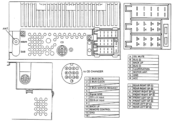
Autórádió bekötés Elektrotanya
2 connection diagram, Fig. 7 connection diagram Yaskawa Varispeed686SS5 CIMRSSA User Manual
![]()
wiring diagram needs for 01 rubicon 500 Honda Foreman Forums Rubicon, Rincon, Rancher and

XMaxx Battery Voltage and Temperature Sensor Install (Updated June 2016) YouTube

Dual System (heat Pump With Gas Furnace) Turning Gas Heat On When Cool Is Selected HVAC DIY
OBD2 conversion thread/ 95 GT ecm to 96F150 computer Mustang Forums at

SIMOR Technology cara integrasikan inverter altivar atv12 ke IoT Blynk
Replacing EP2001 programmer with Siemens RWB29 DIYnot Forums
How To Setting up a 12v 30a power supply, and Connecting to your 3D Printer (Part 2 of 2) YouTube

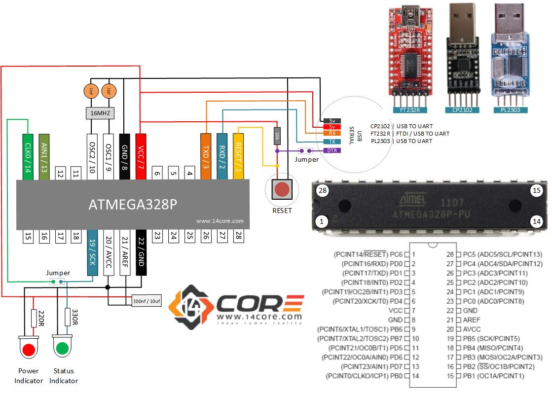
Wiring a Stand Alone ATMEGA328P CMOS 8Bit Microcontroller
How to install a Hive Thermostat to a Vaillant 938 Combi Boiler DIYnot Forums

Schéma electrique fiat ulysse 2 boisecoconcept.fr
Early Valiant Barracuda Club VIN decoding

EX27 Small OHC Engine Technical Information Subaru
How to fit a Honeywell DT90E in place of Sunvic TLX 2259 DIYnot Forums

Wiring a Century Motor 120volts

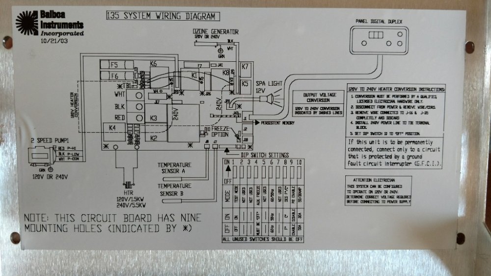
No Pump, But Selenoid Click From Balboa Control Portable Hot Tubs & Spas Pool and Spa Forum


